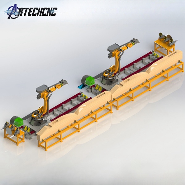
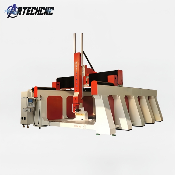
ARTECH CNC COMPANY Customizes Small Robot Arm Operation Model Diagrams to Facilitate Customers' Efficient Application Implementation
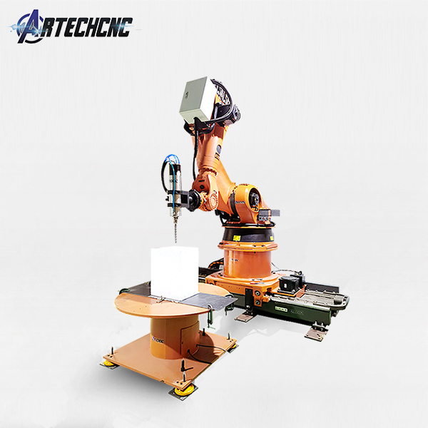
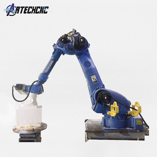
Recently, in response to customers' scenario adaptation needs during the deployment of small robot arms, ARTECH CNC COMPANY has launched a customized operation model diagram design service. Through visualized and detailed diagram presentation, the company helps customers quickly understand the robot arm's operation logic, spatial layout, and linkage process, effectively addressing customers' pain points in equipment installation and process planning, and has received positive feedback from multiple cooperative customers.
This diagram design service originates from actual customer needs. Previously, some customers reported that although small robot arms are compact in size, when it comes to details such as operation trajectory planning and linkage with surrounding equipment, it is difficult to accurately grasp the information only through text descriptions. This often leads to repeated adjustments after installation, delaying the progress of production implementation. To solve this problem, ARTECH CNC established a dedicated design team. Combining customers' production site dimensions, existing equipment layout, and processing requirements, the team creates exclusive operation model diagrams for each customized small robot arm.
In the diagram design, the team adopts a dual-dimensional presentation method of "3D labeling + dynamic process", with the core content covering three major modules: First, the spatial layout diagram, which accurately marks the installation coordinates of the small robot arm, the range of its working radius, and the distance from surrounding equipment such as conveyor belts and workbenches. It even indicates the reserved operating space for equipment maintenance. For example, in the diagram for an electronic component processing customer, the minimum safety distance between the robot arm and testing equipment is clearly marked as 0.8 meters to avoid collisions during operation. Second, the operation trajectory diagram, which uses lines of different colors to mark the movement paths of the robot arm in different processes such as grabbing, handling, and processing. For instance, to meet the loading and unloading needs of a hardware accessory customer, the diagram uses red lines to mark the grabbing trajectory and blue lines to mark the placing trajectory, while also indicating the operation speed parameters at key nodes. Third, the linkage logic diagram, which shows the signal interaction process between the robot arm, PLC control system, and sensors through arrows and timing labels. For example, it demonstrates how the robot arm is triggered to start the grabbing action after the sensor detects that the material is in place, helping customers clearly understand the coordination mechanism between devices.
To ensure the practicality of the diagrams, the design team also conducts multiple rounds of communication and adjustments with customers. A medical device manufacturing customer requested the addition of "emergency stop area labeling" in the diagram. The team immediately optimized the design, using yellow warning boxes at the edge of the robot arm's working range to mark the location of the emergency stop button and the reset path of the robot arm after triggering. Another food processing customer, due to high humidity in the workshop, needed supplementary installation guidelines for the robot arm's protective devices in the diagram. The team also added detailed labels such as the size of the protective cover and installation fixed points in a timely manner.
"The diagram has given us an intuitive understanding of the robot arm's operation, and there was almost no rework during installation," said the production director of a precision component customer. With the help of the operation model diagram provided by ARTECH CNC, the installation and commissioning cycle of the small robot arm was shortened by 30% compared to the expected time, and no efficiency issues caused by unreasonable layout occurred after put into production. Currently, 12 customers have successfully completed the deployment of small robot arms through this diagram service. Among them, 8 customers reported that the diagrams also helped front-line operators quickly grasp the equipment's operation logic, reducing training costs.
The person in charge of the design service at ARTECH CNC COMPANY stated: "The efficient application of small robot arms not only requires the accuracy of the equipment itself but also the scientific nature of early planning. The operation model diagram is precisely the bridge connecting equipment performance and customer scenarios." In the future, the company will further optimize the diagram design service. It plans to introduce a lightweight 3D model function, allowing customers to view the dynamic operation simulation effect of the robot arm by scanning the QR code on the diagram. At the same time, combining the industry characteristics of customers, more exclusive labeling modules for segmented scenarios will be added, such as anti-static area labeling for the electronics industry and heavy material grabbing adaptation labeling for the automotive parts industry, to continuously provide customers with more accurate and convenient implementation support.

